Posts

Showing posts from November, 2017

#43 - Animation - Animation Techniques 3

Image
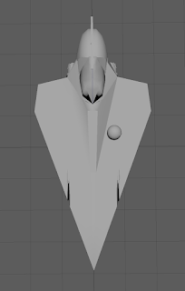
In this post I will show the outcome of my first attempt using handles in a Maya animation, and using the graph editor tool to manually improve the speed of the object movements in the animation. I began by quickly making a door, using the add divisions tool  to add rectangles into the front before extruding and bevelling them. The reason I made a door is because I wanted it to be much clearer what was happening, and a cone might have just looked more like it was spinning as it is perfectly round. The door only took 30 seconds to make. This turned out to be a good idea as the resolution in the rendered video was terrible - more on that shortly. I created a NURBS 2D circle and moved it to the bottom left corner of the door, in line with where the hinges would be. In the Outliner window, I made the door object (and the little sphere used for the door handle) child objects of the 2D circle. I added the sphere in just to show that all objects follow the path of the parent object, not

#42 - Animation - Animation Techniques 2

Image
For one of the class exercises I have created a short animation of a ball bouncing a couple of times before coming to a stop. By completing this animation I have learned how to use key frames effectively. I did not come across any problems with Maya as far as animating the ball is concerned, however I did have an issue which was because of my own attention span lacking. To match the ball object to the template I would simply use the move, rotate and scale tools  to squash the ball in the right direction. After setting every frame, I would re-position the ball before moving the slider up to the next frame, meaning when I went to move the slider it would undo all the changes I had made to the ball. As a result I had to reshape the ball twice for most of the individual frames, except for those where the ball was round. Once I had matched the ball to the template for each frame, and changed the settings so that the animation would play in real time at 30fps, the animation was running

#41 - Model Texturing - Jedi Starfighter 1

Image
When I attempted to begin texturing my first model, I ended up with absolutely no progress. This is because for some reason Maya will freeze if I so much as click on something sometimes. I have no idea why it is doing that but it is preventing me from getting any work done at the moment. I did initially try to split the faces on the body of the star fighter up using the multi-cut   tool, so I could texture the model using the patterns on the images I am using for comparison. Once I had the faces split up, I tried assigning a Lambert to a single face. This is when it started freezing frequently. I did manage to get the colour to change, however it changed the entire model rather than just the face I have selected. I will have to look into changing single faces before I continue. Unfortunately, this texture error is kind of irrelevant due to Maya freezing again and losing all of the progress. At least it wasn't much progress, as I couldn't do much without it freezing. I was

#40 - Animation - Animation Techniques 1

Image
To begin learning some techniques for animating my models I have created a sky dome, which will be used in my actual animation to represent the space around the models in the animation. A huge sphere with a space texture inside will contain the whole animation. This is a very easy and very effective way to create the scenery for my entire animation, although space can be very simple and repetitive. I didn't have any trouble creating this sky dome, as the instructions I had were simple and clear, although it is still a major component of my animation despite being made so easily. I created a sphere and enlarged it quite a lot, so you could fit about 1000 default grid spaces inside. I decided to smooth  it three times, so that later I can use the UV editor to map the texture more easily. Three times wasn't too much for the system to handle. I did not delete any of the faces on the sphere because for a space environment, it needs to surround everything with no gaps. I also use t

#39 - Blog Review - Liam Gilliland - 1606003

Image
I have decided to review a fellow student's blog in the hope that it will also help me improve my own blog. After reading through many of his individual blog posts it is clear that he has maintained a consistent structure throughout. This structure consists of  high levels of descriptive detail showing the reader exactly how he performed a certain task, supported by a very good number of screenshots, and then a short evaluation at the end. liamgilliland123.blogspot.co.uk The way Liam has separated his modelling processes into sections is very clear; the reader can see in the title exactly which part of the model is going to be described, and then it is, as promised. The descriptions Liam has written are very detailed, and they are clearly split up further between images so you can tell which image he is referring to. Another thing Liam has done which could benefit him greatly is at the beginning of the process he did lots of research about Star Wars, Maya 2017, and all the to

#38 - Summary - Invisible Hand

Image
I will now summarise the development process of the final Star Wars model, the Invisible Hand, and explain and justify the reasons I have for leaving it how it is. Generally speaking, the entire model is quite smooth, and doesn't have a lot of detail.This is for two main reasons. Firstly, the schematic I was using, and other images which I viewed, of the ship do not have many details on them either. In fact the schematic I used was the only one available. The whole body of the ship is indeed smooth, and there are no geometrical extrusions around it. Secondly, the actual shape of the model, especially the front, was very difficult to get right, and used a lot of polygons to get the right curve. To make it rounder from the front perspective would have cost a lot of rendering time, and according to my storyboard the model is never seen at this angle anyway. Therefore I decided to limit the number of faces around the ship from the top and front views, and have more from the side view a

#37 - Assignment Models - Invisible Hand 3

Image
Now that the front and the back halves of the ship were created and connected, I was able to cut out the hole in the back for the hangar, which is a crucial part of my storyboard, where the Jedi star fighter flies in. Luckily, as I had a lot of difficulty with the front of the ship, I was able to get the back of the ship just right so that in the animation the hangar should look very good. I did originally plan to make a large shape to use to cut out the hangar, using boolean difference , but fortunately the faces I already had were in the perfect position to be simply deleted. I then used the bridge tool  to close all the new gaps that could be seen inside the ship, creating a floor, walls and a roof inside. As the bump around the hangar had already been created, this was essentially all I had to do to create the hangar, and the resulting size matches the schematic. There were not any engines on the schematic, so I created them using my own imagination (and comparing to some Goog

#36 - Assignment Models - Invisible Hand 2

Image
Once the front half of the ship was finished I moved on to the back half. Again, I began with a cylinder, except this time instead of scaling each side individually I dragged the vertices on each line all together to match it to the size and shape of the front view schematic. The bottom of this cylinder was flat some I moved the bottom edges of the cylinder downwards, and so on all the way around. Once I had the shape right, I extruded the faces around where the hangar would go, and then  target welded the outer edges back to their starting point, leaving it curved around the side of the new faces. The back now had the bump that is clearly visible around the hangar. I also simply extruded certain faces from the top and bottom of the ship to create the shape of the wing by using insert edge loop to add enough vertices to form the shape. Then, for both the top and bottom fins, I extruded up again, then extruded the new faces outwards, then up again, and moulded it into the right shape by

#35 - Assignment Models - Invisible Hand 1

Image
I have begun modelling the final Star Wars ship on my list, the Invisible Hand. Before I even explain how I created it, I'd like to note that I found this part of the model incredibly difficult to make because of its long, round shape, and balancing the polygons was near enough impossible for someone of my skill level, so it will not be perfect at any stage. However I have got it into a state which looks like what it is supposed to, and it is recognisable as the Invisible Hand. Here are the schematics I used: https://www.deviantart.com/tag/starwarsclonewars https://www.deviantart.com/tag/starwarsclonewars https://www.deviantart.com/tag/starwarsclonewars I imported the schematics into the view port, which I had to cut from the same image online, and managed to get them all on the same scale, unlike the other two models. This is helpful because I should be able to balance the shape from all perspectives without having to guess. I started with a cylinder and essentia

#34 - Summary - Venator Star Destroyer

Image
Now that the Venator Star Destroyer model is complete, I will outline what went well, what problems are remaining and overall why I am satisfied with the model as it is. The tool I found the most useful for creating this model was the mirror tool , largely because it cut some of the work literally in half, but also because it made positioning many of the objects much easier. For example, with the bumpers around the ship, I was able to reflect one bumper down to place another directly underneath, then reflect them again onto the opposite side of the ship. One problem I did have with this tool was that it would offset the rotation tool, making it very difficult to rotate the reflected bumpers into the right position near the end, and unfortunately some of them are not quite right, but it is by such a small amount that it will ever be noticeable in the animation, and it was still much quicker than duplicating them and moving them over. In fact, it would only be noticeable by zooming in

#33 - Assignment Models - Venator Star Destroyer 7

Image
This is the final post for the Venator destroyer explaining how I created to central tower on the back of the ship, and then the final details around the back. I adjusted the size of some of the middle faces on the top of the model using connections , then extruded  the resulting faces upwards. I the dragged the vertices on the top corners of the extrusion inwards to match the schematic, and added some extra vertices in the middle to ensure I got exactly the right shape, where it bends slightly. A point I would like to mention early in this post is that the schematics were still not scaled to match each other completely, so from the front view, the tower seems slightly wider than the schematic, as well as from the side view, and the top view is offset by a fair bit. However, I have used my own judgement to balance the size of the tower as accurately as possible, and it has turned out quite well. The shape and size are close enough between the three perspectives that it looks like a sta

#32 - Assignment Models - Venator Star Destroyer 6

Image
In this post I will outline the process of creating the engines for the Venator - of which there are ten. Conveniently, all of them are perfectly round, so I was able to use cylinders very easily to create the shape of each of them. The general process was using the extrude tool  to pull the edges of the cylinder out, then forwards, then down again, or perhaps into a cone, until I had matched the shape on the schematic. Bear in mind that because I cannot seem to get all of the schematics on the same scale, I am matching the engines more closely to the top view schematic, with the exception of the two engines furthest from the center of the ship because they were simply too big to fit on from that viewpoint. I made them slightly smaller, then matched them to the side view schematic. As a result of this the engines may seem unbalanced, but on a ship that size with so many different variations it might be closer to the official thing anyway. Once the shape of the cylinder was correct,

#31 - Assignment Models - Venator Star Destroyer 5

Image
Now for the last of the three sub sections on the front of the model, the central bridge. There was really not a lot to do on this bit, as most of the details will be textured. Like with the previous sections, the details are so flat that there would be no point in even implementing them, as without texture they would be invisible against the grey mesh anyway. All I had to do for this was add some new edges along the bridge using the connect tool , then extrude the faces made between these new edges down. I did have to take care when moving vertices across (for the new edges) because the front of the ship has a downwards incline, so I had to drag both across and down or up to keep the ship straight. Otherwise, it was this simple process in five areas running up the ship. For the last area, I had to add divisions  as there were chunks in between that were not lowered in the schematic, but I extruded  all the faces between these chunks. Once that last section was extruded  I was don

#30 - Assignment Models - Venator Star Destroyer 4

Image
The next section I worked on was the lowered middle area of the main body of the Venator destroyer. The only objects that are worth modelling on this section are the eight turrets and the eight boxes that go between them (I'm not entirely sure what they are, but they are a similar size to the turrets so definitely need to be modelled, and I will refer to them as side cubes). As for the rest of this section, I might pull up a couple of areas if the shadow on the schematic looks thick enough, but otherwise all of the details can be added with textures. Judging by my storyboard I doubt these textures will be visible at any point in the animation anyway, so I could just ignore it entirely without ruining the animation (not that I plan on doing that). I created these first as they looked less complex than the turrets, and they in fact were very easy to do. I simply placed a cube primitive, and used the bevel tool  on the front face so that I could move the vertices back and form the poi

#29 - Assignment Models - Venator Star Destroyer 3

Image
In this post I will focus on the details I added on the main body of the Venator destroyer. I used the multi-cut tool  to trace the outline of the inner surfaces of the ship as depicted on the schematics, and turned symmetry on so that it would add the new edges on both sides of the model, ensuring perfect symmetry. This worked for most of the model, however at some points it would not allow me to place a new vertex, so I had to turn symmetry off and finish both sides individually. I think this might be because the schematic I am using is not quite symmetrical itself, as I cannot seem to align them all properly at all. I can easily overcome this by moving the schematic slightly each time I swap sides. Not an ideal work around, but it is sufficient for achieving symmetry. I also use the method of dragging opposite vertices next to each other to make sure they are perfectly in line, before I move on to modifying the shape. Once I had the outline cut out, I extruded  the middle bit down s

#28 - Summary - Jedi Starfighter

Image
I will now summarise the whole process of creating the Jedi star fighter, focusing on the main issues that are left, and clarifying things that have been done deliberately, so that there is a clear reason for everything done throughout the process. I will also surmise how successful I feel the model is overall. It could be argued that the main body of the model does not have that much detail, especially near the front where it is all flat, but this is because the actual model is flat, and all of the shapes seen on images of the star fighter are in fact painted on, or textured. When I come to texture this model, it will suddenly seem far more detailed, but there are currently no physical differences in the models geometry, as far as I am aware. Bear in mind that for things like the raised area in the middle of the ship, on the top face, I had to judge myself where it should be because the two schematics I have are different. As for the cockpit, it will become quite clear upon viewing

#27 - Assignment Models - Jedi Starfighter 8

Image
If all goes well, this should be the last post about the modelling process for the Jedi star fighter. The only remaining things to model were the R2-D2 bot sat in the wing, and the hydraulic landing pads, which I decided to have visible as in the animation the star fighter will land in the hangar of the Invisible Hand. Firstly, I began creating the front hydraulic landing pad using a cylinder, which I scaled down to the size of the top segment of the lander hydraulic tube. Using the multi-cut tool,  I cut a ring inside the cylinder's bottom face at 20% from the outer ring, then  extruded  the new inner faces down the length of the inner tube on the schematic. I then reversed this process where the tube got fatter by extruding the edges sideways, then extruding the outer faces downwards until the tube was at the right length. Then, similar to the previous stage, I extruded the outer ring edges downwards at a 45-degree angle to create the cone shape on top of the landing pad. To cr