#19 - Modelling - Modelling Techniques 4 (F16)
These are the finishing touches of my F16 model: the tail fins, the engine, the wheels, the missiles, and the cockpit. For the tail fins, I essentially repeated what I did with the main wings and used the multi-cut tool to add vertices to the point where I needed to drag the shape out without distorting the rest of the body of the F16. I then dragged out these vertices with the move tool, then the next vertices up, then finally dragged out the flat edge to the back of thee model where the fins ended. I re-shaped them a bit using the move tool, but otherwise they were the right shape. Like with the main wings, I could have used the mirror tool but I chose to simply do the process twice because it was a very quick and easy addition to the model. I then selected the vertices along the back end of the model which were in line with the tail fin from the side view image and pulled them up to different heights, creating the fin shape. I used the scale tool to make it a lot thinner, and then the tail fins were finished. I did have a small problem when moulding the second of the two side tail fins because I could not remember exactly which order I dragged the vertices in, but eventually I got it right. This is why the mirror tool would have been more useful but in all honesty, I had complications with that in the past and decided it would just be quicker to do them manually.


Next I focused on the cockpit, which was the last part I needed to model using the body object that was already in the scene before moving on to attachments. I selected the faces in the middle of the model which were in line with the cockpit from the side view image and scaled them to be slightly bigger, then pulled them up slightly. I used the smooth tool to make this entire section much more rounded, then began to deselect the outer faces, pull the remaining ones up, and deselect some more until I was just pulling up the very middle bit, creating the rounded cockpit shape on the model. The smooth tool was very useful for making the cockpit much more rounded rather than having just a flat box on the top of the F16, although it wasn't as round as it could have been. To make it rounder would add an unnecessary number of polygons for a practise model however, so I'm choosing the lower quality but better performance balance for now. If I were to do it again I would attempt to use a bezier curve to create a perfectly rounded 2D cockpit outline before adding a planar and extruding it, then shaping that model, likely resulting in a more curved and accurate shape.

The final sections of the F16 were all attachments, using new primitives, and therefore were all quite easy to create. For example, the engine was literally just a cylinder which I rotated, shrunk, and moved to the right position. I did use the extrude tool to push down every other face around the cylinder, just to give it a more wholesome appearance, but it is still pretty basic.

For the missiles, I did use a tool I hadn't used before. Firstly, I elongated a cylinder primitive, then used the multi-cut tool to add vertices at the back of the cylinder to pull out a couple of faces to become fins. Once I had the first fin, I used the mirror tool to reflect another one on the x-axis to the other side of the cylinder. I then tried to do the same for the other two fins but because that required a different axis, I couldn't figure out the right settings after many failed attempts. Instead, I duplicated what I had, rotated the new one 90 degrees, then used the combine tool for the first time to combine the two objects into one, with fins on all four sides. I rotated it 45 degrees so that the fins looked like an X shape, like in the schematics, then duplicated that and added them both to a wing of the plane. Using the combine tool might not have been the most effective tool, as it could leave me with twice as many polygons in each missile, with half of them completely hidden. Nonetheless, they look perfect, and they are very small models anyway.

Lastly, I created the wheels underneath the model by adding in another cylinder, which I shrunk in all directions then made circular, and a final cylinder which I shaped into a long pole. I duplicated these twice, so there were three of each, and moved them into their appropriate positions, rotating the poles where necessary and making the front wheel slightly smaller like in the schematic. These wheels have absolutely no detail whatsoever, however the schematics give no indicator to detail and there's only so much you can do with wheels and axles anyway.

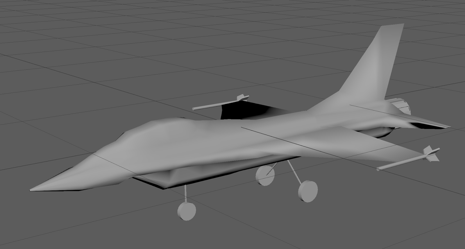
Now, the F16 model is finished. There are a lot of things that could have gone better, but it was not a bad outcome either. I did try using the smooth tool to give the entire model more curvature, but unfortunately it just made it look more like an alien spaceship like something out of Halo, with a ridiculous number of polygons, so I reverted it back to how it was before. Mainly the problems were at the beginning when I had to have three attempts at getting the body shape right, and next time I will be sure to take my time in measuring the dimensions with my eyes and also making the original cylinder a more ideal shape to be modelling, such as making the middle faces on either side wider so that when I come to extruding the wings I actually have more thickness to work with. I also could have made the attachments much more detailed, however it would be a waste of time at this stage as it is just a practise and I have many other tasks to complete, and the model, as seen below, looks more or less like an F16.


Comments
Post a Comment