#17 - Modelling - Modelling Techniques 3 (F16)
In this post I will show how I created the F16 model using the techniques explained in the week 4 lecture and worksheet. I began by using the three-view editing method and importing images of the F16 schematic into the work space. There was a top view for the X axis, a side view for the Y axis, and a front view for the axis. Using the view, import image tab in each separate window I imported these three images in and aligned them so they formed a box inside which the F16 images were lined up.

I then added the three background images to a new layer together so that I can turn them off if needed. In my opinion, it is easier to just turn x-ray on for the actual F16 model, or simply move it up if I need that to be solid, rather than constantly selecting between the toolkit tab and the channels tab. Nonetheless, the option to hide the background images is there if needed. In this case, there will be no point in the creation process where I don't want the images to be there as I need to get the dimensions perfect.

Now that my work space was prepared, I began to create the shape of the body of the F16. I instantiated a cylinder and resized it so that it roughly matched the size of the central span of the F16 images on each axis. Then, using the insert edge loop tool, I placed a few rings along the cylinder and one by one scaled them out until the model size matched the size of the top view image. As you can see in the image above, there is a problem with scaling the whole ring of edges out. It has totally ruined the shape of the other two sides of the model, however this should be easily fixed by simply flattening or widening the very top edges of each ring, until a flat but solid shape is left.

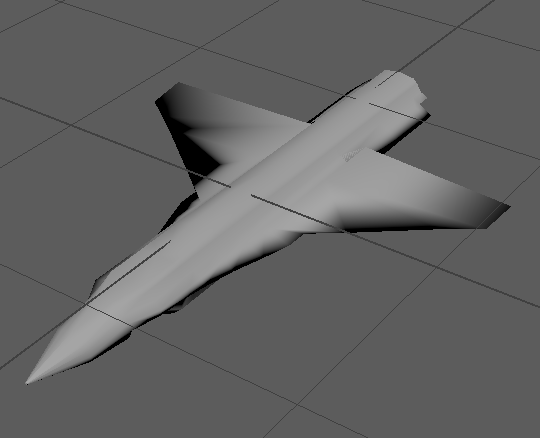
In direct contradiction to the previous paragraph, I have totally restarted my F16, only this time I pulled up only the central vertex on each side rather than the whole ring. Then, I scaled the faces in between the ridges that had been created and moved the vertices along each edge from front to back out until I had a more curved, fattened shape for the body of the F16, as seen above. Once the body was accurate, I began work on the wings. I used the multi-cut tool to place a vertex part way up the edge where the wing first comes out of the body. I then used the move tool to pull this vertex out, then the next one along as well, to form the shape of the wing. Once the middle of the wing had a straight edge I pulled that edge out to the back of the wing, then slightly altered the position of another vertex, leaving me with a nice wing shape. I then repeated this process for the other side, and the wings do look the same, however some of the edges were positioned in different places when pulling out new edges. I have simply deleted them so they match, taking care not to remove anything important.

Looking back, it might have been much better to do one wing and then mirror it, as this would have saved time, ensured symmetry and prevented the edges and vertices being generated in different places. However, the model itself looks symmetrical enough, any differences will not be noticeable as they would be down to a pixel or two. All that remains to do now is the tail wing, the engine, the cockpit, the wheels, and the guns on the wings, all of which are quite small tasks.

I then added the three background images to a new layer together so that I can turn them off if needed. In my opinion, it is easier to just turn x-ray on for the actual F16 model, or simply move it up if I need that to be solid, rather than constantly selecting between the toolkit tab and the channels tab. Nonetheless, the option to hide the background images is there if needed. In this case, there will be no point in the creation process where I don't want the images to be there as I need to get the dimensions perfect.

Now that my work space was prepared, I began to create the shape of the body of the F16. I instantiated a cylinder and resized it so that it roughly matched the size of the central span of the F16 images on each axis. Then, using the insert edge loop tool, I placed a few rings along the cylinder and one by one scaled them out until the model size matched the size of the top view image. As you can see in the image above, there is a problem with scaling the whole ring of edges out. It has totally ruined the shape of the other two sides of the model, however this should be easily fixed by simply flattening or widening the very top edges of each ring, until a flat but solid shape is left.

In direct contradiction to the previous paragraph, I have totally restarted my F16, only this time I pulled up only the central vertex on each side rather than the whole ring. Then, I scaled the faces in between the ridges that had been created and moved the vertices along each edge from front to back out until I had a more curved, fattened shape for the body of the F16, as seen above. Once the body was accurate, I began work on the wings. I used the multi-cut tool to place a vertex part way up the edge where the wing first comes out of the body. I then used the move tool to pull this vertex out, then the next one along as well, to form the shape of the wing. Once the middle of the wing had a straight edge I pulled that edge out to the back of the wing, then slightly altered the position of another vertex, leaving me with a nice wing shape. I then repeated this process for the other side, and the wings do look the same, however some of the edges were positioned in different places when pulling out new edges. I have simply deleted them so they match, taking care not to remove anything important.
Looking back, it might have been much better to do one wing and then mirror it, as this would have saved time, ensured symmetry and prevented the edges and vertices being generated in different places. However, the model itself looks symmetrical enough, any differences will not be noticeable as they would be down to a pixel or two. All that remains to do now is the tail wing, the engine, the cockpit, the wheels, and the guns on the wings, all of which are quite small tasks.


Comments
Post a Comment