#26 - Assignment Models - Jedi Starfighter 7
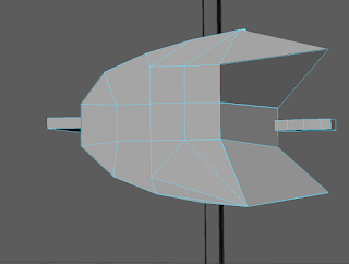
The process of adding the back section of the Jedi star fighter was very long and tedious and came with a whole list of problems. I decided that in order to achieve the right curve, I would have to use a bezier curve again, although this time I am confident I was much more successful in using it than when I made the cockpit. This is because I remembered to adjust the pivot point of the new object before using the revolve tool. I also set it to only revolve from 270 degrees to 360, so that only a quarter of the full ring appeared. The first big problem was that this new shape didn't have a bottom, so I used the same bezier curve, added a planar to it, extruded it slightly, then after using the combine tool to make it the same object as the revolved object, used the target weld tool to attach each vertex on the flat shape to the bottom of the revolved shape to give it a face. What I did not realise until it was too late was that many of the new faces were black, and needed reversing. However, when I used the reverse tool, even with only a couple of faces selected it would reverse the entire object. So, I found a work around by extruding the faces out very slightly then using the target weld tool to put them back into their original position, only now the face was grey. Unfortunately, this didn't work on all of the faces, presumably because they would cut into each other slightly, but none of these are visible at all on the finished model, so I decided to leave it. I know this is not the best solution but it does not affect the visual quality of the model, only perhaps the processing requirements, so I am compromising for now. The revolved model also created a few extra faces in the corner where the other 75% of the model would have been, because the bezier curve must have been slightly off, but I was able to scale them to appear as if they are not crossed over a half way line. The final problem with this object was the presence of extra edges after having to use the extrude tool, but I was able to target weld all of these out, leaving a geometrically stable object with a couple of reversed faces.


I think it turned out quite well. I certainly have the shape right, which is good because I was very concerned that I would not be able to get a good enough curve, but from the side the curve is quite high poly, with sufficiently high poly from the top view as well. Not as high poly, as I had to sacrifice this to avoid higher render times, but I chose to have less quality on the top because any views from the top will have part of the model underneath it anyway, taking attention away from the exact resolution of the curve. From the side view, there is nothing in the way or behind the curve, so it needs to be slightly higher quality. It also looks slightly like it's been pushed inside the main body, but because of my limited schematic views, I have had to balance it between the position on the top view and the scale on the side view. This is another case where, like with the cockpit and the engines, I have had to decide where the object should go. If I have time to remake this particular object, which will be the first thing I come back to if I do, I will be sure to reverse the planar curve before using the combine tool to connect it to its 3D counterpart. I will also try and improve the exact shape of the bezier curve to avoid edges crossing over each other in the corners. Otherwise, the shape and scale is correct and the position is balanced well.
Update:
I have discovered that in the reverse tool options you can set it to only reverse the selected faces, so I went back and fixed all the issues mentioned previously involving reversed faces. Everything to do with the extruding and the target welding when trying to find a workaround is now redundant. If I had thought to look for this solution much earlier it could have saved me a lot of time and trouble, but at least now the object is improved and I know for the next time.

To add the tail fin, I simply created a cube, then scaled it to be flat and the same size as the back object. I duplicated the back object, then tried using the boolean union tool to cut the shape of the back out of the tail fin, but it would just delete everything. I know from experience that this is because the back object has some geometry issues, probably the reversed faces. I simply used the bezier curve to create another object by revolving it, this time going the full 360 degrees to ensure its correct geometry, and used the boolean intersection tool to cut out the shape. I used intersection instead of union because the new revolved object was entirely reversed, but it didn't matter because it was to be deleted anyway. I then adjusted the tail fin slightly so that there were no gaps between it and the back object, then used the combine tool again to make them one object. I then moved it into position on the main body and it looks just about right.

Update:
I have discovered that in the reverse tool options you can set it to only reverse the selected faces, so I went back and fixed all the issues mentioned previously involving reversed faces. Everything to do with the extruding and the target welding when trying to find a workaround is now redundant. If I had thought to look for this solution much earlier it could have saved me a lot of time and trouble, but at least now the object is improved and I know for the next time.


Comments
Post a Comment